Once in my life I have visited Vienna. Even though I have been living in Austria for almost 2 years. I didn’t even live in Austria when I was visiting. It is actually much eaiser and faster to get to Vianna if you live in Munich. Which I did at the time. Vorarlberg is basically on the opposite side of Austria from Vienna. And Austria is WIDE.
Anyway. I was in Vienna. They have this very nice and super convinient subway system. But it is also quite old. So old that they still have some pretty outdated displays, looking from todays standards. But they are beautiful!
I cannot even describe what they look like. It’s this cool pattern that makes me think of victorian times or something similar. Like a design worthy of a king! I took a picture of it.
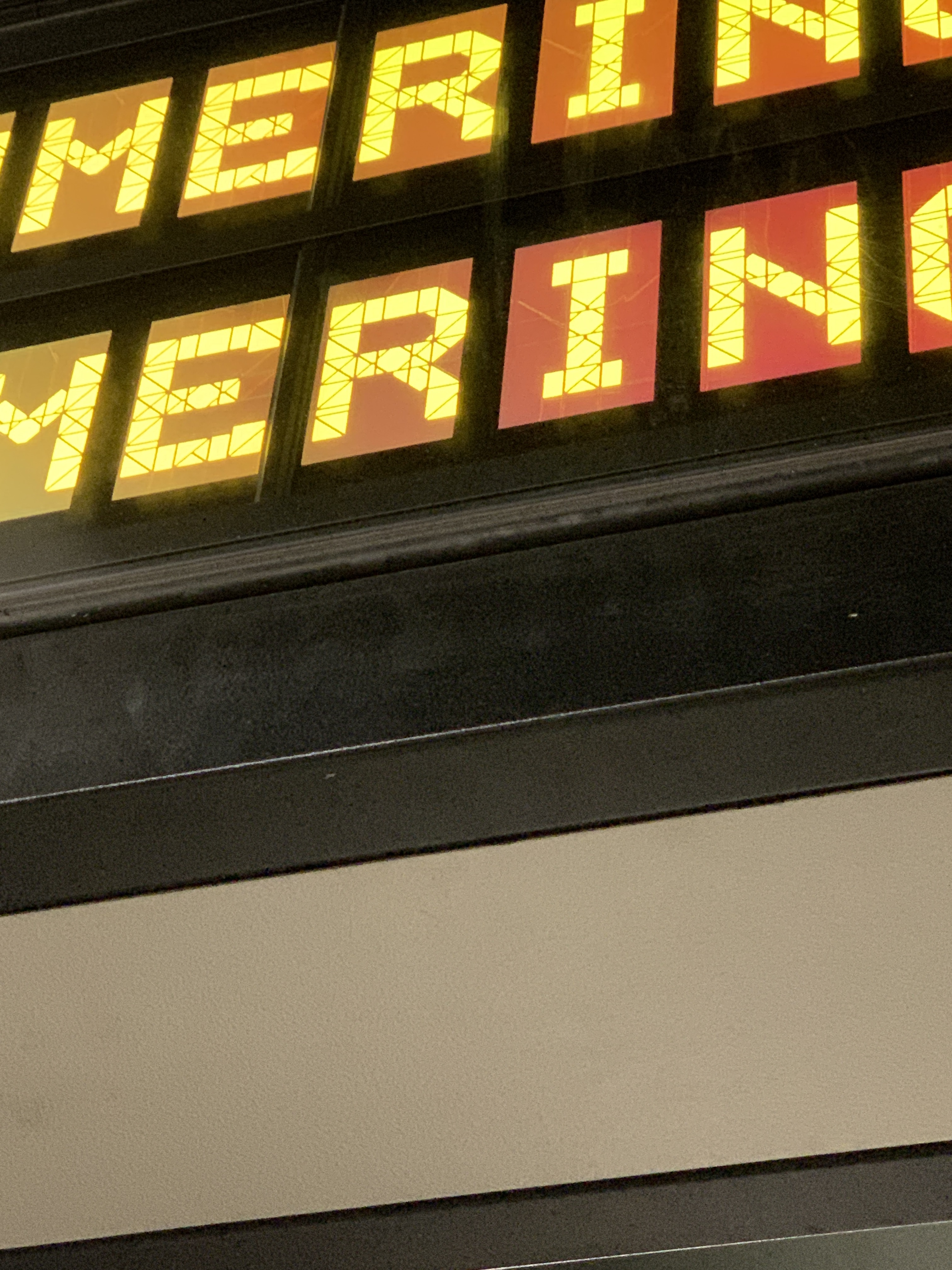
Vienna Subway Display
Pretty cool, huh?!. So naturally, when I got home, I wanted to find out if I could get my hands on such a display. But, as my search would end up showing, no one makes this cool stuff anymore. I did, however, find out that these kinds of displays are not only installed in Vienna. They are also in many train stations in Spain. Though, there are different versions of them. Which is just even cooler!
I don’t know how many different segments were in the Vienna sign. But there were a lot! easiest way to find out would have been to see all of them lit at the same time.
What I did find during my search of the display, is what let me to the project that I am about to tell you about.
I found multiple posts from people who are making cool displays. One of them included the most perfect website for display nerds. It’s hard to explain exactly how cool it is. But the tool on the website basically allows us to use different multi-segment displays and then see each character displayed.

The example above is shown with the same display that I would like to recreate.
The thing
What is this project/thing I have been talking about then? Well, it’s more or less trying to replicate one of those displays that have been generated for the tool that I linked above.
And what do I mean by replicating it? Seeing it on the computer is fine and the tool is really amazingly built. Someone has really put some energy into finding these displays and taking them with us into the modern era. But wouldn’t it be cooler if we could build or own version of these displays. Using modern technology such as WiFi control and LED lighting?
I think that would be so cool. And apparently, so did someone else. Someone built this victorian age looking display and I would very much like to do the same. Just not the same style of diplay.
To me, the style of the Vienna subway diplays were much cooler and looks so much more complicated given the sheer number of segments. So when I saw that the webiste tool already has a 43-segment display graphic that looks very similar to the one from Vienna, I knew I had to build it.
There are display graphics, as you can see on the tool that has many more segments than 43. It might look even more like the one from Vienna. The problem here would be creating the seperation of the lights between the characters. If we don’t want to build a display that is gigantic. Say we want something that can be a nice addition to a living room shelf. Then we don’t want to max out on the size.
We also want something that could maybe be printed on a 3D printer. So we also need to stay within the bounds of a normal consumer printer, so that more people could hopefully benefit from the end product.
Can we even make the frame?
The first thing that I wanted to investigate, is whether the frame is do-able. When I say frame, I mean that physical thing that is going to create the seperation between the lights. The lights that will light up each individual segment of the display.
We don’t want the light from one segment to bleed into the other. This will cause the display to not look as appealing and nice. Best is that all the light from the LED in one segment is only used to light up that segment.
As the first step to find out, I took a screenshot of the 43-segment display in the website tool with all of the individual segments lit up
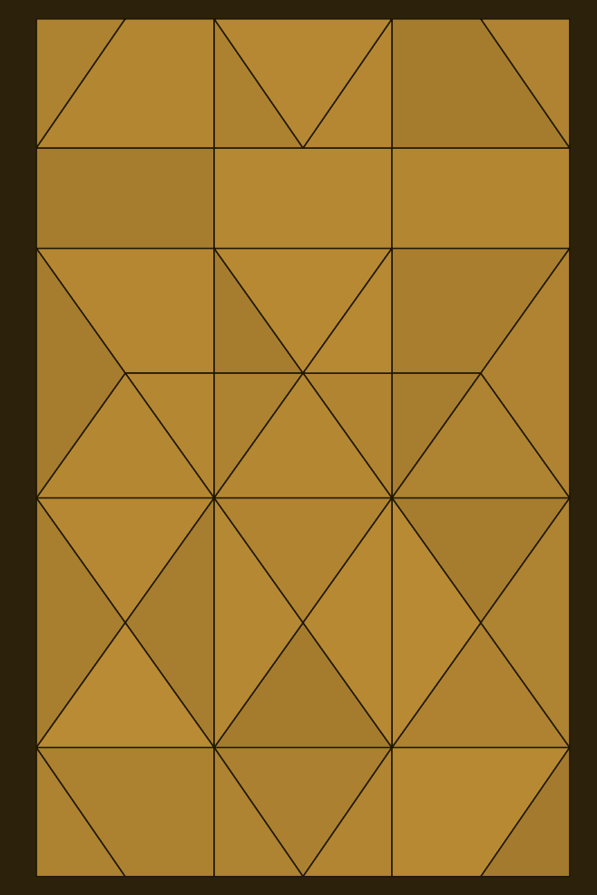
Then I was able to import this image into a sketch on OnShape, the online CAD tool that I use and have talked about before in other blog posts. Having done this, I could trace construction lines on top of all black lines seperating the segments on the screenshot.
Don’t get me wrong. I am not a CAD expert and figuring out the best way to do this too time. A lot of time. Because OnShape does not give you an easy way to extrude directly from lines when many of them intersect. So I needed to create offsets of the center lines that I had drawn on top of the screenshot. I could then use the construction lines to set the offsets and all of the constraints needed.
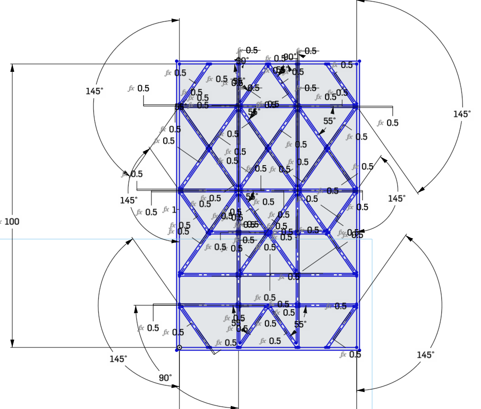
I also parametrized the sketch such that I could easily change the width of the frame and create thicker walls in between the segments.
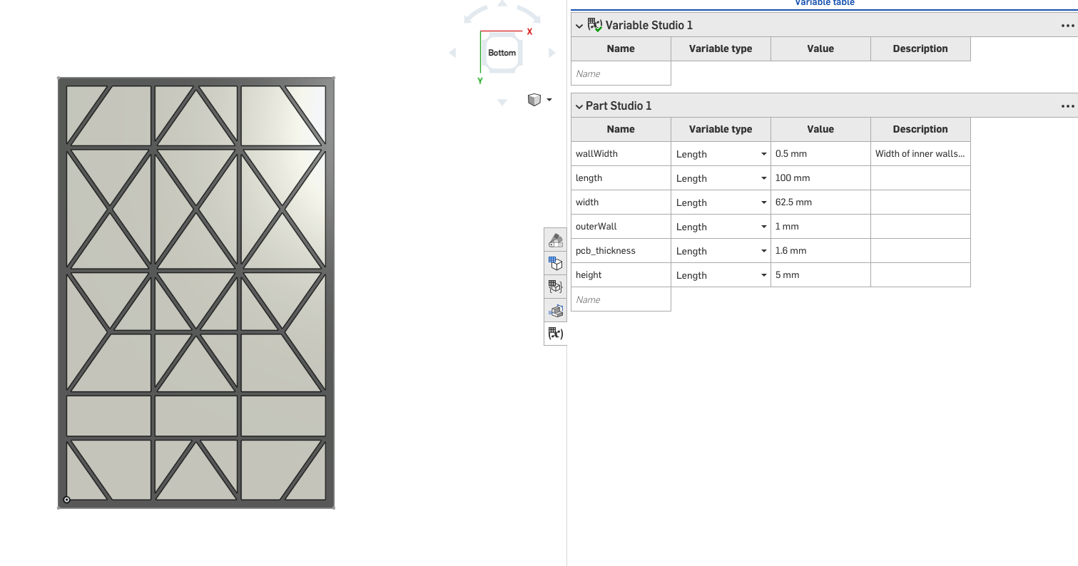
Only thing left to do, was to decide how big I wanted the first prototype to be. This changed a lot during the design process. But it actually wasn’t until I had the first 3D print finished that I saw how freaking tiny it is. Because I started by printing a piece that was roughly 5 cm in length and 2.5 cm in width. This meant that the “compartments” for the LED segments became super super small. So very small SMD LEDS needed.
Having seen this, I thought it would be quite small for a prototype. When working with such things, it is always nicer to have a bit of room and not start by using the tightest tolarances possible. So I reprinted the design, but his time with a length of 10 cm and a width of roughly 5 cm. This came out just as good but the tolerances were a bit bigger. Meaning I will be able to put in some larger LEDs.
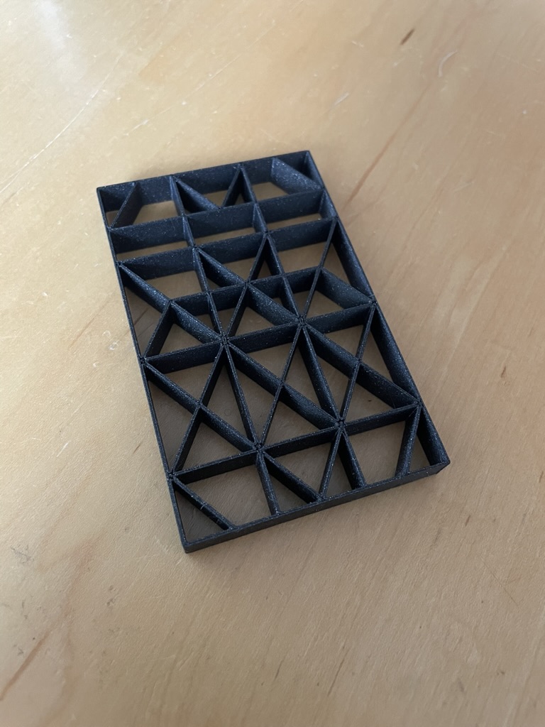
In the end, I think we can definitely use this to try this out. The frame looks very promising. For now, I have not been able to check how much light bleed there is between the segment. We need to paint it anyway to increase the reflection of each “compartment”. Since the material I used for printing is almost black, there will not be a lot of light reflection bouncing off the walls.
Lets make a PCB
For it to shine, we need lights. Lots of lights. We need to fit 43 LEDs onto a PCB and also make sure they don’t interfere with the frame. We would also like to have the most uniform light distribution in each of the pixels in our display. So I’ll try to put the LEDs toward the middle of each pixel.
But before we can create the PCB, we of course need a schematic.
Somehow we also need to control the LEDs. I mean we could just light all of them up at the same time, but what fun would that be? For the final thing, I would wish to have a sophistacted system so we can easily connect more of them together.
But for now, we just need something for the proof of concept and that we can debug on.
So, let’s start by creating our schematic design. First of all, we need something to drive the LEDs. Power supplies is a good start, but we don’t want a power supply on the board for debugging. We just want to be able to suuply the board from an external supply. First order of business is then to insert a connector where we can connect power, ground and some digital control signals.
How many signals do we need?
Well, that depends on the scheme we choose for the LED control. For the prototype, I have chosen to use a STP16CPC26M from ST. This is a constant current sink for the LEDs. The current can be set using an external resistor. Meaning we can potentially connect a potentiometer or we can just be lazy and change out the resistors manually until we find a good value. It is also super easy to supply with 5 V and ensure 20 V driving capability from that. By setting the resistor, we can also adjust the current from 5 mA to 90 mA. That should be plenty.
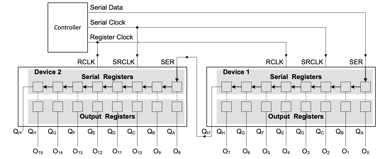
The constant current sink basically works like a shift register over a serial protocol. Meaning we have a serial to parallel converter. I found an application note from TI that describes how to connect multiple of them together over longer distances. Simply perfect, since this would be the end goal anyway.
So the signaling of the prototype can be designed according to the application note. Of course there will be slight differences since the devices are not the same. But in the end, a shift register is a shift register.
Follow along in Part 2 :)