On my third semester we really started to dig down in all the fun analog electronics stuff. In fact we had a whole course about discrete components. So naturally our project was going to involve a lot of those. Our 5 man group decided on making a HiFi Amplifier. But because this being AAU, we had to have some sort of thoughts about the UN world goals in the project as well. Now the only thing that makes sence from an efficiency point of view today is a class D amplifier. But that is basically taking an analog signal, making it digital and then making it analog again. That was no fun. So we decided on making a Class G amplifier.
This type of amplifer uses two sets of rails as supplies. This means that for low volumes, you would be on the low voltage rail. For higher volumes, you would be on the high voltage rail. This ended up being quite the challenge with a lot of late nights at the end of the semester. We ended up with a product that somewhat worked, but shouldn’t be tinkered to much with while on!
We started off by making the circuit on a PCB on the mill at the university. However it proved hard to make any changes since we often had to mill a new one. When we finally had a working board, we accidentally fried a couple of transistors and never got it working again. So to save ourselves some headaches, we nailed the hole circuit up. Like in the good old days. Now it was much easier to get the oscilloscope in a do some probing.
We started out by building a preamp. The idea was to have no voltage amplification and simply have so we didn’t put any load on the playback device. The consisted of a simple common collector setup. Which gave us a voltage amplification of around 1. This is the preamp circuit we designed
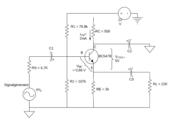
Corner frequencies were designed to be at 1.06 Hz and 17.47 MHz. The circuit has a 2 mA queisant current going through the transistor to keep it open.

Next we build a bass and treble adjustment circuit. This meant that the user had tone control of the device and could amplify and reduce the bass and treble frequencies. The design was based on the legendary Baxandall tone control design.
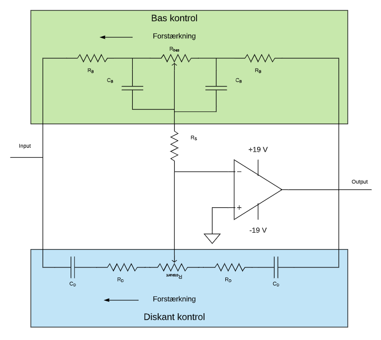
Bass resistors and capacitors were identical on either side of the potentiometer. The same for the treble passives. We used a TLE2072 for the opamp to get a good amount of gain at the high treble frequencies. Something went wrong when doing our calculations though. We couldn’t figure out what. But simulations and measurements showed the circuit working as expected.
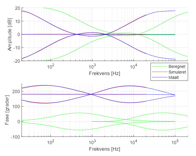
Our measured result was pretty bang on the simulated result. But our calculations seems to have been shifted.
The power amplifier was made up of all discrete and passive components. Mostly BC547 and BC557 transistors, except for the outputs. The first stage was a differential amplifier which took the input signal and a feedback signal from the output. This was loaded by a current mirror. Next stage was voltage amplification made up of a common emitter circuit with a PNP transistor coupled to the positive rail with the emitter leg.
A VBE-multiplier circuit then kept a compound coupling upon to drive the output stage.
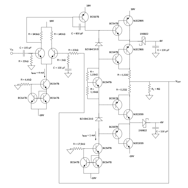
The circuit shows that we used 19 V for the high rails and 6 V for the low rails. The VBE-multiplier was held open with a current mirror as well. This is actually not the final schematic as it never made it into our report. It turned out that we needed a regular 1N4148 diode between the BC547B/BC557B transistors and the VBE-multiplier in order to switch properly between the rails.